Every synth needs a VCA. Since I've been making a few modules around Alfa chips that are largely clones of Curtis chips I picked up some AS3360's to use for this module. The AS3360 has two VCAs in it. It's fairly simple to use compared to the VCF and VCO in the same series of chips.

Much of the design is straight from the data sheet with some bits borrowed from the Look Mum No Computer VCA but I've changed some elements to deal with CVs in my system going 0-10V and for various component differences.
As usual I put this thing together on the breadboard first. In this case it's pretty much a complete mockup of what I have in the PCB.

The PCB design goes quite smoothly when I can work out the details on the breadboard. The best part of looking at the LMNC design before going into the PCB design was realizing that that design inverts the input and inverts the output for a net non-inverted output. That's a nice simplification I wish I had thought of myself, it's probably common on lots of modules but the first time I've seen it and understood it.
Here's a simulation of the input CV circuit. And another simulation of the output which is a bit different from other modules I've made since the chip provides a current output.


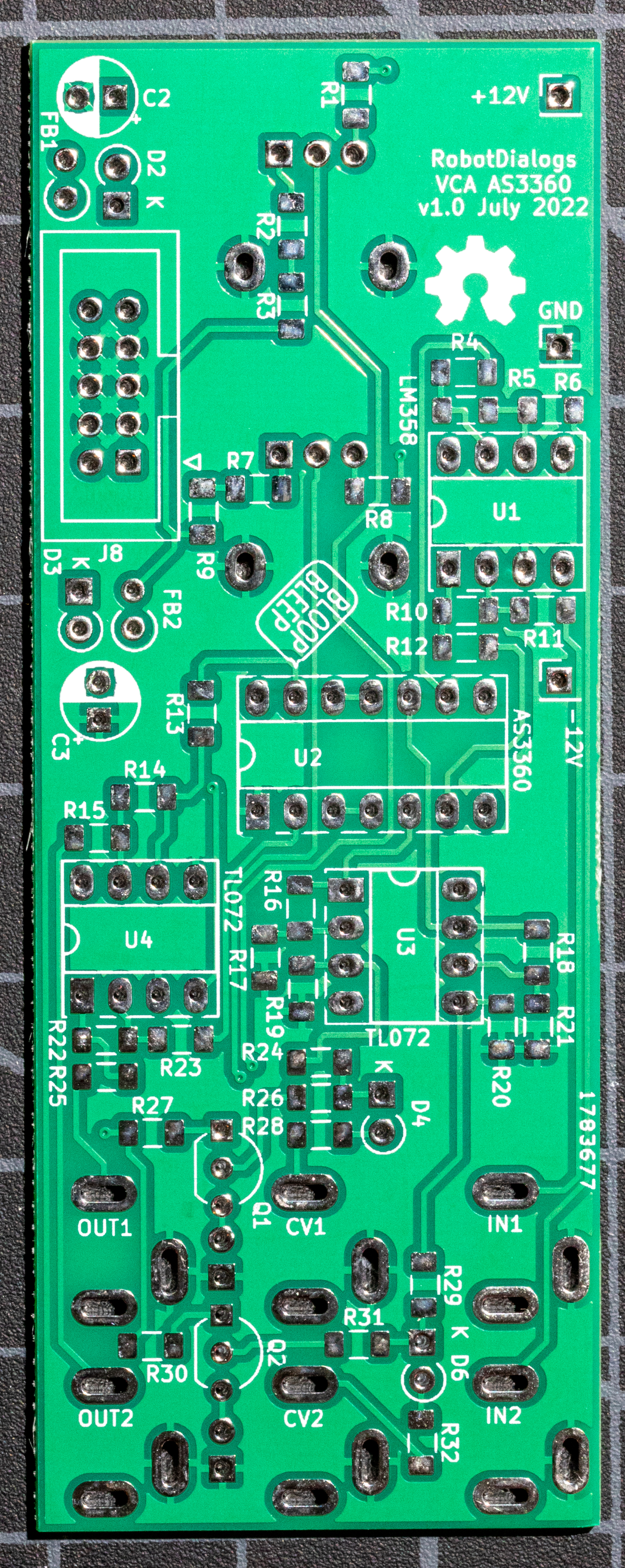


- The voltage divider for the CV's shows 400k and 50k resistors (R24/R19 and R29/R20). After some testing, 390k and 33k worked better. The v1 values didn't account for the gain on the non-inverting buffer correctly.
- On the silkscreen U1 and U3 are both op-amps but the chip name TL074/LM358 are swapped.

This work is licensed under a Creative Commons Attribution-NonCommercial-ShareAlike 4.0 International License.
Comments
Post a Comment
Comments are moderated. Comments containing links are marked as spam.