I needed more space.


I designed this thing in FreeCAD which was an exercise in frustration but the end result was pretty good. I've used FreeCAD quite a bit since this project and it did help me learn a lot of the quirks.
The main idea was that every piece of wood or metal had to be a separate part in the Part Design workbench with sensible coordinate frames for assembly. Then the Assembly workbench brings it all together. I designed the top and bottom as separate assemblies so that that there was a bit more modularity and the weight would be manageable.


Once I had the design done I had the opportunity to get this cut on a friend's CNC and in the same weekend got to play a bit with sand mold making and metal casting. To prep for that I whipped up a mold pattern for my logo.

The most important part of this was getting a workable draft angle and nice fillets to allow the pattern to pull from the sand mold. I have no experience with that but I watch a foundry on youtube regularly that talks about this stuff all the time so I made educated guesses and it worked. The pattern was 3D printed in a resin printer.


You can see a maker's mark there by the L, that's Columbo who's workshop made the casting and CNC work possible.
Here's the CNC the cabinet parts were milled out with.

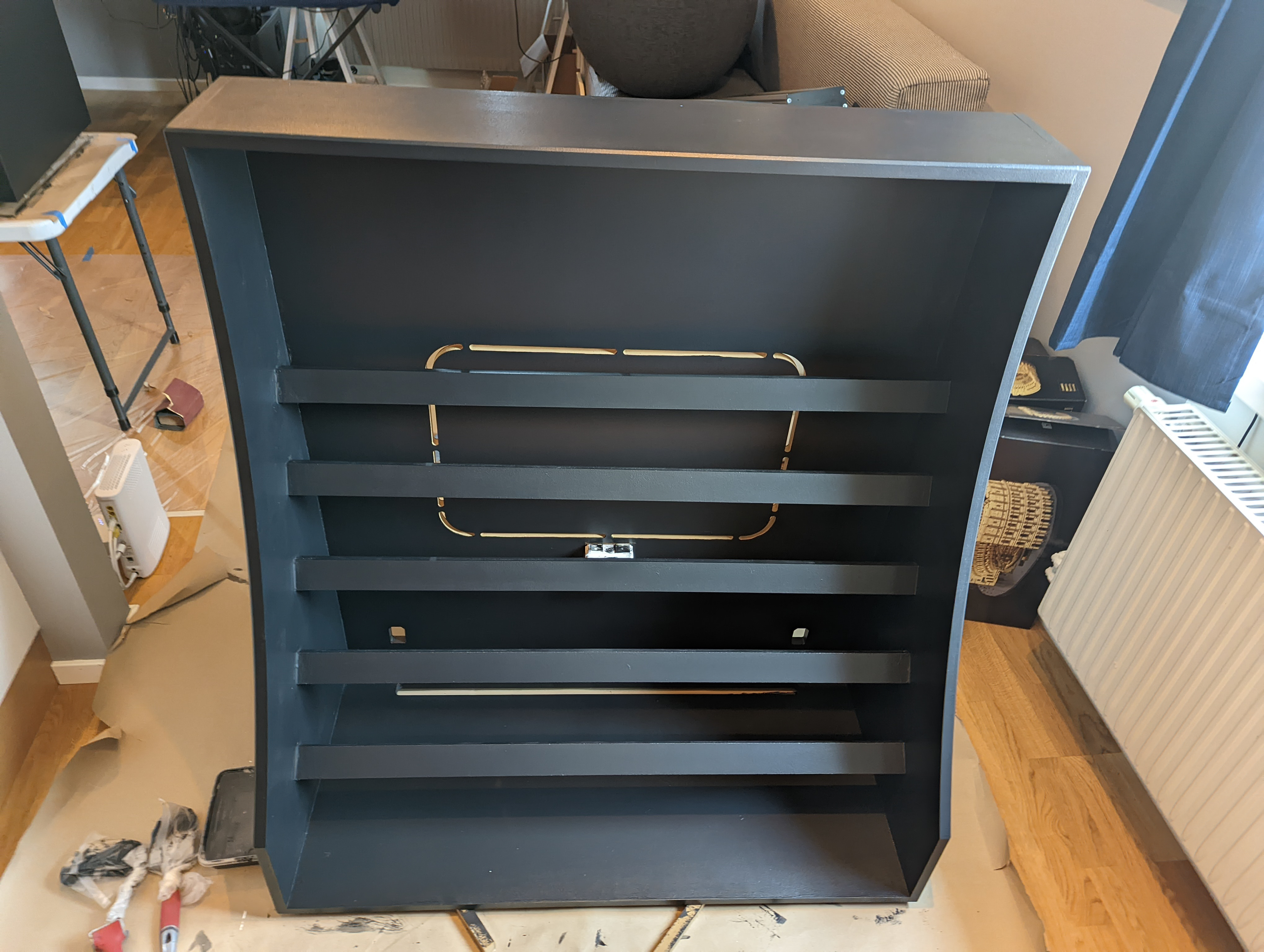
With all the parts cut out I went about assembling this thing in my living room. It was tight quarters for a few days...


With everything glued and screwed I went over all the edges with a router to knock the sharp corners off and puttied over the screws.
Painting also was tricky, black paint in the living room makes me paranoid.

After a few coats of paint I started in on the wiring. The top half has seven rows for a total 21U x 196HP. Each row has two of the power distribution PCBs I designed and there are four Mean Well RT65B power supplies for the top. There are two rows of 12V LEDs in the interior which I've found very useful when plugging things in and finding things dropped inside the cabinet.

On the bottom half I've installed standard 19 inch server/network rack rails which will accept all the existing rails and other equipment in the first photo as well as a bunch more equipment like audio interfaces and what not. This adds another 15U on each side with 84HP available (but not the way I use it). That brings the total up to an absurd (10x84)+(7x196)=2212 HP.

It's heavy and honestly a little top heavy. Initially I was going to have the casters inset in the bottom half to lower the height a few centimeters, but I didn't have them before the CNC was available so that didn't happen. Now that it has equipment in the bottom it doesn't seem unsafe, but initially, on the high quality casters it felt a little tippy. If I had to do it again I'd make it 10cm deeper.


I also designed a modular cable rack that I could 3D print (this time in black PLA) to fit the sides. On the old rack I had a metal cable rack I found on the web, but I've had bad luck with cable racks (that was the third web find) so I just made my own. I also stocked up on patch cables from Polar Noise which I've been happy with.

The only thing left to do was fill it with stuff...or so I thought. After putting all my gear on the rack and some new stuff, I started to trip the breaker. As it turns out, the initial current draw of all the caps in this thing is significant but brief! I borrowed a clamp on current meter that I could use with my oscilloscope and measured the current spike...


That's over 30 amps when the switch is flipped! (The meter is 100mV/A and the scale here is 1V per division). This was a little tricky to measure because half the time you power it up when the AC is at a low point and you can't get the spike to trigger and the other half the trigger hits but the breaker trips.
Anyways the result of that test shows the need for some sort of inrush limiter. I bought a DIN rail mounted ICL-16R - AC Inrush Current Limiter because I couldn't find a suitable alternative.

One final mod to the cabinet which I wasn't sure would work out was adding this shelf to accept my Roland System-8. Here's what this thing looks like today (spoilers).

The design files for this cabinet are available here: https://github.com/EchelonForce/eurorack_cabinet
And also on thingiverse.
The cable rack can be found here: https://www.thingiverse.com/thing:5492713
I would estimate the overall cost of this was about $800, with the rails and power supplies being the bulk of that.

This work is licensed under a Creative Commons Attribution-NonCommercial-ShareAlike 4.0 International License.
Comments
Post a Comment
Comments are moderated. Comments containing links are marked as spam.