This is a big one. I have been pursuing an idea to make all the modules in a full Eurorack signal chain and to be able to do polyphonic voices in it. The first thing in the that chain is a midi module that can take midi from the computer or keyboard and turn it into signals for other modules.
Early on I needed a module like that so I bought a Befaco Midi Thing kit from Thonk and started using it, but I wanted to have the ability to drive even more outputs.
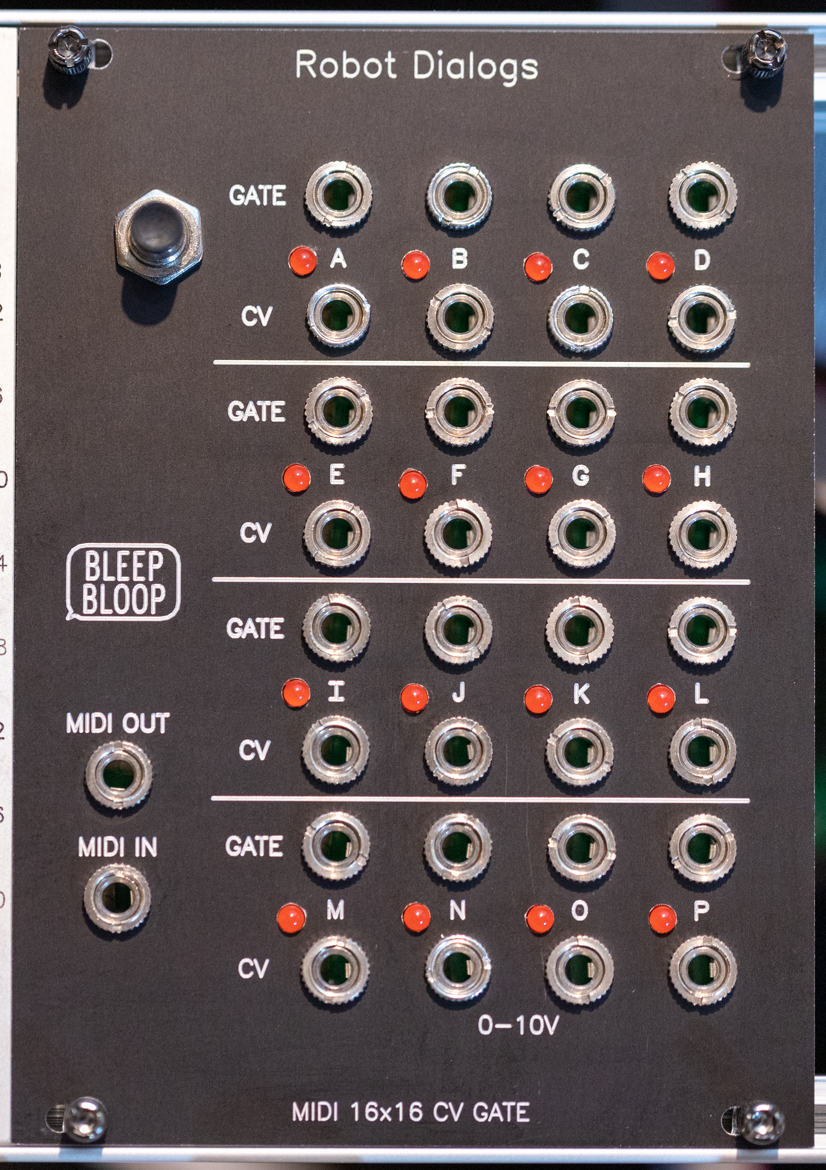
So this module has 16 CV outputs and 16 Gates. It consumes 18HP. It has MIDI input and output. the brains of the operation is an Arduino Pro Mini which I've written firmware for to handle polyphonic input (more on that later). There's a single button on the front which for now lets me set a MIDI channel. This thing doesn't have nearly as much configurability as the Midi Thing but I don't have to open a manual to change the main thing I need to configure.
Design Process
This design is much more in my comfort zone than most of the analog modules. The 'hard' part of this one is the digital design and code, but that's my day job so it's a place I can flex.
Like most of my designs this one starts on the breadboard.

Obviously there aren't 16 outputs on that breadboard. There's an Arduino and a breakout board for a MCP4922 DAC and some LEDs. I used this breadboard to sort out the driver code for the DAC.
When I went from breadboard to PCB it got complicated. One issue is component shortages, I couldn't find the MCP4922 or any DAC good enough for this at the time in a surface mount package, so I went with the DIP through hole package instead. Driving 8 of those (they're dual output DACs) and 16 gates presents challenges for the Arduino Pro Mini because it doesn't have enough pins. So the PCB also has two 74HC595 Serial to Parallel shift registers for that stuff.
Every available pin on the Arduino is used in the v1 PCB for this design, but two of them (A6 and A7) are not actually usable the way I intended. They can't be outputs so the LEDs I wanted to drive with them can't work.
In the end there were 28 ICs, 34 jacks and more than 200 resistors on this PCB. Even splitting it into two PCBs and using surface mount components for most things it was a challenge to layout and route. Here's a screenshot from in the middle of the design (many components changed along the way).

With each module I get a bit better at the layouts. Now I start with the front panel components to get them in the best locations and then the through hole and finally the surface mount. That general order makes it a lot less likely to need to redo a whole bunch of layout and routing. I probably rerouted portions of this PCB at least 3 times to get it to work though.
There are simulations in the schematic for the output stages, but they're pretty simple, the CVs and gates are amplified to my desired CV range of 0-10V (almost). There's a flaw in the CV output circuit though, more on that later.
 |
 |
 |
 |
 |
 |
 |
 |
Code
- The MIDI channel can be configured. Press and hold the button for 5 seconds and the current channel selection will blink on an LED. Press the button to change to another channel. Press and hold the button to exit and save the selected channel. The channel config is persistent through power cycles.
- The incoming MIDI traffic is passed to the output ('Thru' Midi).
- Incoming note on/off messages are the only messages processed. Each simultaneous note goes to the next available output until all outputs are used up.
- There are some test programs available in the repo for checking new builds.
- Pressing the button in normal operation stops all notes. This is handy for some midi interfaces that don't send note off commands reliably.
- A 16 output sequencer mode, I'd have to figure out how to program new sequences.
- A 16 step sequencer mode.
- A multi-channel mode listening to 4 midi channels and output in 4 independent polyphonic setups.
- Handle pitch bend commands
- A drum rack mode (like polyphonic midi, but notes fixed to specific output pairs). Maybe use CV for velocity or simple envelope in this mode, or just more gates.
Testing
- buffer at 1024, 22ms jitter
- buffer at 512, ~12ms jitter
- buffer at 256, 6-8ms jitter
- buffer at 128, ~5ms jitter


- Some LEDs are misaligned, not on the 14mm grid.
- A6 and A7 on the Arduino can't be used as digital outputs, so LED1 and LED2 don't work.
- A6 and A7 could be used on V2 for a sample and hold function and or a clock input function or for calibration.
- LED1 and LED2 probably need to be removed, unless some of the pins tied to control signals for the DAC or 74HC595s can be used instead.

This work is licensed under a Creative Commons Attribution-NonCommercial-ShareAlike 4.0 International License.
hi, is this availabe for sale?
ReplyDeleteNope, it's all open source for anybody to replicate. Maybe someday I'll make kits or a few to sell but no plans at this time.
Delete