A quick update now that I've received version 2 of the Level PCB. (For more info see v1 details here.)
The PCB with LEDs is virtually identical to the v1 version. The only real difference was that I panelized the design to get more of them for v2.

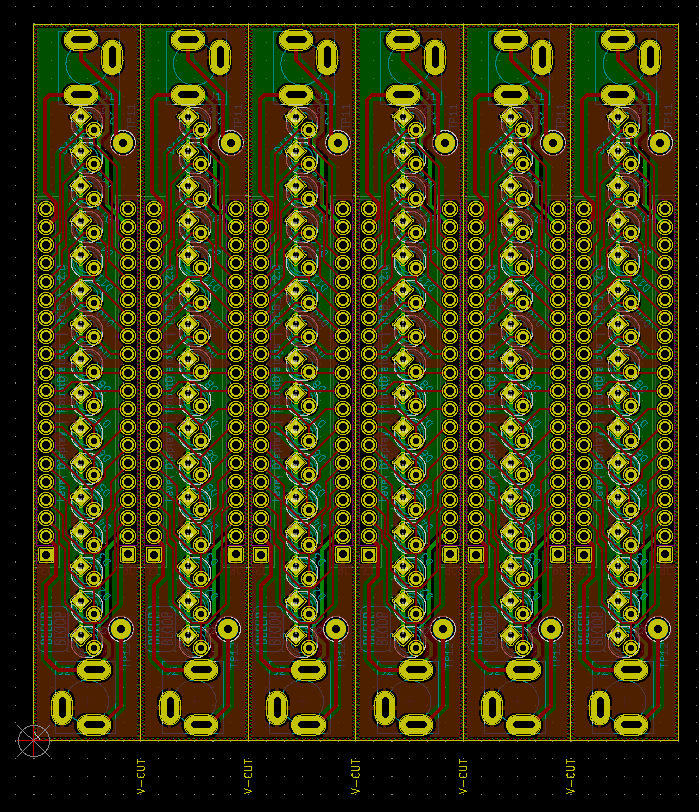
On the PCB that handles signals and power, a lot of changes were made.
- Used different footprint for resistors.
- Used wider footprints for caps I have that are 5mm pitch.
- Avoided collisions between the arduino header footprint and other components.
- Moved the 20pin header to allow for less depth overall.
- Used more consistent trace sizes.
- Added a path between the two potential inputs that can be jumpered so that the two inputs are multipled together. In using the module I find two inputs unhelpful typically. When the jumper is bridged, R20, R21, R22 and C2 aren't required.
- Removed a log of capacitors.
- Removed the 5V regulator, and rely on the arduino pro mini's regulator.
- Removed power LED.
- Removed mounting holes.
All of that allowed for a PCB small enough to panelize and reduced the overall depth considerably.


If I ever make a v3 I think a CV input might be useful. It could be picked up on the analog inputs of the Arduino and displayed on the LEDs similar to how the tuner modification in the v1 post works.
On the software side I haven't changed much. When I use the jumper on v2 to multiple the two inputs together I disable the other input (A7 usually) so that the update rate is better and there aren't and noise issues from a floating pin.
With the help of a friend the front panels are also evolving. We're figuring out engraving the labeling and also combining multiple of the modules on the same panel.


Comments
Post a Comment
Comments are moderated. Comments containing links are marked as spam.