When I bought the AS3310 chips from Electric Druid for the polyphonic envelope I also bought a few other chips to experiment with. One that I expected to be a pretty straight forward project to set up for a module was the Noise2.
The chip is just an 8 pin PIC preprogrammed to output white and pink noise. There's a thorough writeup on the development of the firmware here.
Only 4 pins on the Noise2 are used and it's all 0 to 5V so interfacing is pretty easy. I wanted both filtered and unfiltered white noise and a pink noise output all buffered to prevent undo current draw on the Noise2 chip and amplified to 0 to 10V in my setup which required 3 op-amps. That left one op-amp available so I also have an inverted filtered white noise. With 4 outputs the jacks on the module could be on top and bottom and support the PCB properly.
The filter in this case is a simple RC low pass filter straight off the data sheet.
I went about simulating the circuit and then breadboarding it to confirm my schematics.
Simulation of the filter and output buffer with inversion: see it live


- Surface Mount Resistors
- Ceramic caps first, the solder points are below sockets on the top side.
- IC Sockets
- Diodes and Ferrite Beads
- Polarized Caps
- 2x5 Power Socket
- 7805 Regulator
- Jacks, aligned to panel
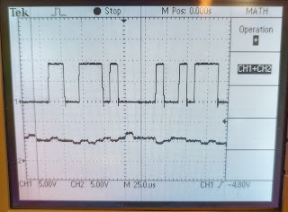
Unfiltered White Noise and Pink Noise
Filtered White Noise and Inverted Filtered White Noise (with math adding them together there in the middle).
The depth is ~32mm but can be improved with a lower profile 5V regulator... something to change in v2.
Other thoughts for a v2:
- Use better footprint for polarized caps.
- Add alternate 7805 footprint for T0-92 or surface mount.


Comments
Post a Comment
Comments are moderated. Comments containing links are marked as spam.