This build was inspired by this post from ElectroDruid, at least in part. I have been getting into sound synthesis over the past year and needed simple module on my Eurorack setup that I can plug anything into and see if it's working (or peaking). There are a few modules out there like what I've made here but I'm doing most of my synth as DIY kits or pure DIY of my own design.
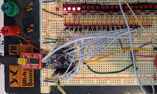
The idea started on the breadboard, and because I had an Arduino Pro Mini in my box of spares that's what I used.
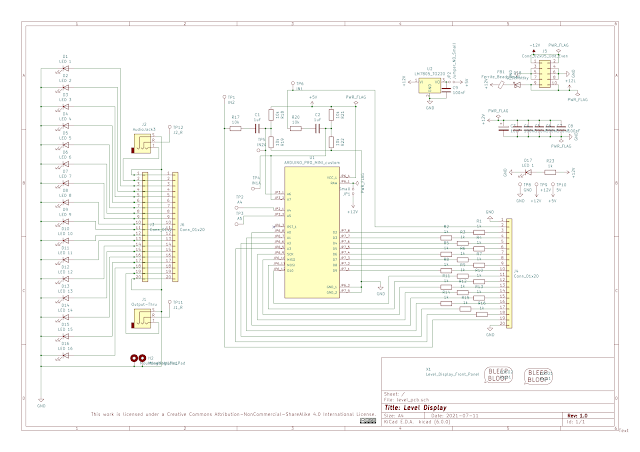
Here all 16 outer pins of the Pro Mini and two of the inner analog pins are connected to the row of LEDs each of which has a series resistor. for a total of 18 LEDs, which was later reduced to 16.
There were still two analog pins available (the green and yellow wires) which were used as audio inputs. The other two analog inputs were later used for some timing/debugging. The audio and control signals on Eurorack can swing ±10V which would damage the Arduino if used directly. To solve that I've used almost the same circuit as the ElectroDruid version but with different values which clamps the signal to +5 : -0.5V for the Arduino.
The Pro Mini I had handy was the 8Mhz 3.3V version, but later I switched to a 5V 16Mz version to improve the sample rate.
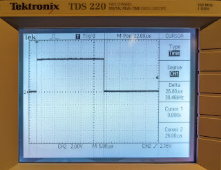
For a proof of concept I started with the built in Arduino APIs, which work but are very inefficient. That initial version only managed to sample at ~2kHz. Eventually after switching to the faster Pro Mini and several iteration of optimization the sample rate was improved to ~38kHz; however, two pins are sampled, toggling every other read, so it's about 18kHz per input. That's not as good as the PIC used by ElectroDruid, but it's plenty for my purposes. Here's a pin toggled with every ADC read showing the final sample speed.
Prior to getting that kind of performance I set the software aside and designed a set of PCBs. This is the first time I've designed PCBs for manufacture. I've only made them for etching before. I figured this was a fairly straight forward design to get some experience on. After some design time and learning how to use KiCad I managed to get a v1.0 I was happy with and had some samples made by Seeed Fusion PCB service. I also spent some time learning how to use FreeCAD and made a footprint or two for this design.
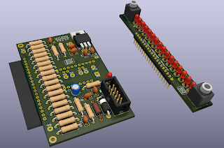
While waiting on the boards to arrive I finished improving the software, ordered the components I needed to make several of them and used FreeCAD again to design a front panel. I initially 3D printed the panel to see if the fit was okay and then had a friend with a CNC mill machine some from aluminum for me. In the software, I also added a peak indicator to the code so fast peaks are more visible. The ~38kHz sample rate came at the expense of resolution which was reduced to 8 bits. There is a lookup table in the code based on
this table. The look up table is used to map the audio level to the number of lit LEDs where each LED covers a fixed value 0dB down to -30dB.
Once received, the v1 boards worked great.
After a few of these were built as intended I decided to make some that ignored one of the inputs and connected the two audio jacks as a passive multiple. This seems to be more convenient than plugging two independent sources in. The v1.0 boards have a 5V regulator on them and some configurable solder jumpers for that but I don't think they are needed, since the power consumption is within the limits of the regulator on the Pro Mini.
Power Consumption on v1:
Peaks (All LEDs on) = 85mA on +12V
Idle (LEDs Off) = 26mA @ 12V
So ~60mA/16 LEDs. LEDs pull 3.75mA each (avg)
On one of the boards I used some alternate firmware to implement a tuner. The tuner is pretty basic, measuring time between zero crossings and mapping that period to notes with a look up table. For that, 12 LEDs were used for notes and 4 for showing the deviation (how far out of tune). It's very convenient and intuitive for tuning oscillators.
After some testing and using the v1 boards and a few months using them I did a redesign in KiCad 6 for v2:
- Used footprints for resistors that are closer to 250mW sizes. There's a lot of wasted space on the board, same for diodes and ferrite bead.
- Use footprints that are correct (wider than v1) for all ceramic caps so they don't have to be bent.
- Avoid resistors for Arduino foot print so they don't run into each other.
- Moved second 20pin header on PCB_B to reduce the depth when plugged in.
- Use small traces for all the led paths, no need to mix and match.
- Add Open Hardware logo.
- Add passive multiple path with solder bridge.
- Removed several unneeded capacitors.
- Removed the 5V regulator and it's support components.
- Changed a bunch of footprints.
- Removed power LED.
- Removed mounting holes in corners.
I'm waiting for the v2 boards to arrive along with 10 other PCB designs... I went a little ham on the PCB ideas.
Some things I didn't try on v2 that could happen on a v3:
1. CV input circuit path (could use LEDs to show semitones and octaves)
2. CV output circuit?
This work is licensed under a
Creative Commons Attribution-NonCommercial-ShareAlike 4.0 International License.


Comments
Post a Comment
Comments are moderated. Comments containing links are marked as spam.